
Safety Through Design
Redundant sensing. Fail-safe detection. Environmental sealing.
Ergonomic safeguards. Every layer of every Linemaster foot control is
engineered to reduce clinical risk.
Explore how structured risk analysis, durability validation, and layered safety
architecture support reliable performance across our full product line.
SAFETY PILLARS
Layered Safety Engineering
Modern medical foot switch systems rely on multiple independent layers of engineering safeguards — each one reducing a distinct category of clinical risk.
These are all ranked and evaluated through the DFMEA process.
Redundant Sensing
Dual Hall effect sensors or dual microswitches provide continuous cross-checking of outputs. If the signals deviate beyond a defined tolerance, the system flags a fault. This condition enables the console to disable output, issue an error indication, or require a system reset.
Electrical Isolation
Electrical isolation is applied by removing any continuity/conductive connection between 2 sides or equipment to prevent current flow. It matters in our footswitch design because it will provide a protective barrier between any user, who is physically contacting the footswitch, and the connected equipment when there is electrical hazard (high voltage/current/power) on the equipment side.
Tilt & Orientation Protection
An internal accelerometer monitors foot switch orientation. If the device is lifted, tipped, or inverted, all input signals can be disabled, preventing unintended equipment activation during repositioning.
Environmental Sealing
Ingress-rated push buttons and conformal-coated PCBs resist moisture and chemical exposure. Gasketed seals, protected cable entries, and enclosure geometry help divert fluids away from seams and actuators, supporting performance in environments where bleach alcohol, glutaraldehyde and other cleaning agents may be present.
Security Protocols
Cybersecurity-focused wireless protocols, encrypted communication, and controlled pairing methods help prevent unauthorized access and cross-room connections.
Pre & Post Travel Band
A configurable pre-travel zone prevents activation when an operator simply rests their foot on the pedal. Post-travel ensures full engagement. Both settings are adjustable in firmware to match equipment requirements.
Explore our safety features with our director of engineering,
Sean Lewis.
Safety isn’t a feature you add at the end, it’s the organizing principle behind every Linemaster foot switch design. This video walks through the key safety mechanisms built into our foot controls, from redundant sensing and tilt detection to environmental sealing and electrical isolation, showing exactly how each design decision reduces clinical risk before it ever reaches the OR.
INTERACTIVE EXPLORER
Safety Features by Design
Learn how each physical design decision on a Linemaster foot control directly addresses a specific safety or reliability requirement.
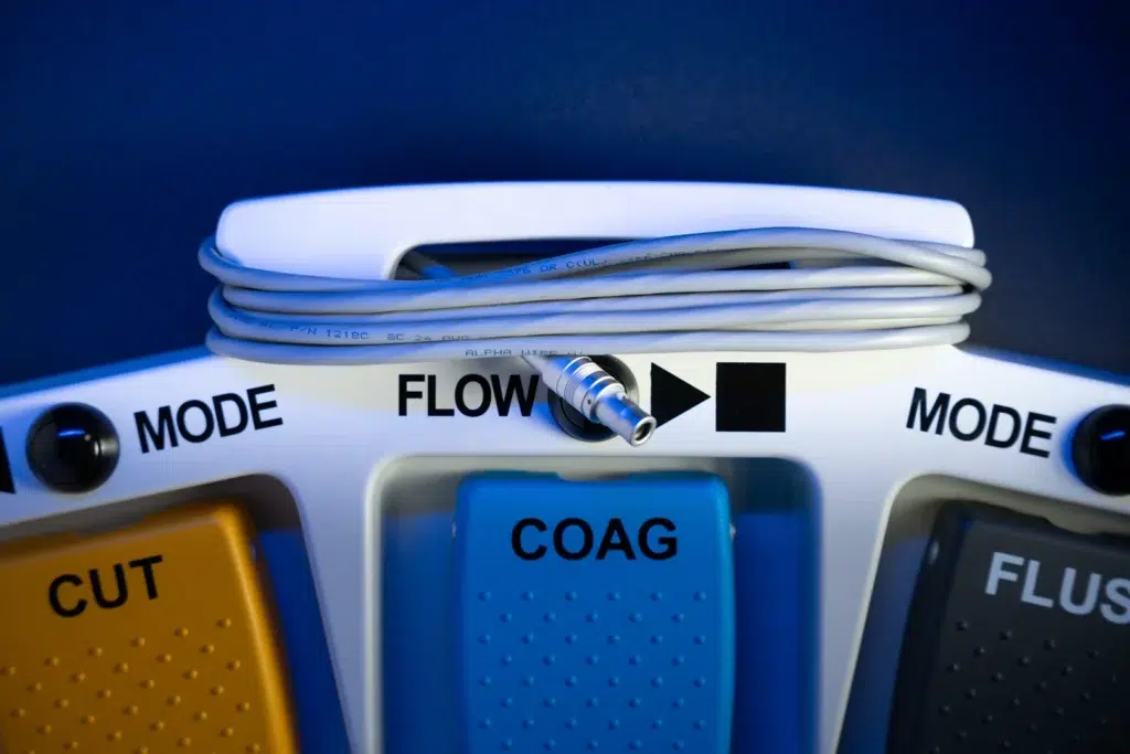
Cable Management
The integrated carry handle discourages lifting by the cable — protecting the cord anchor from repetitive mechanical stress. Structured cable channels also reduce floor clutter and trip hazards in the OR.
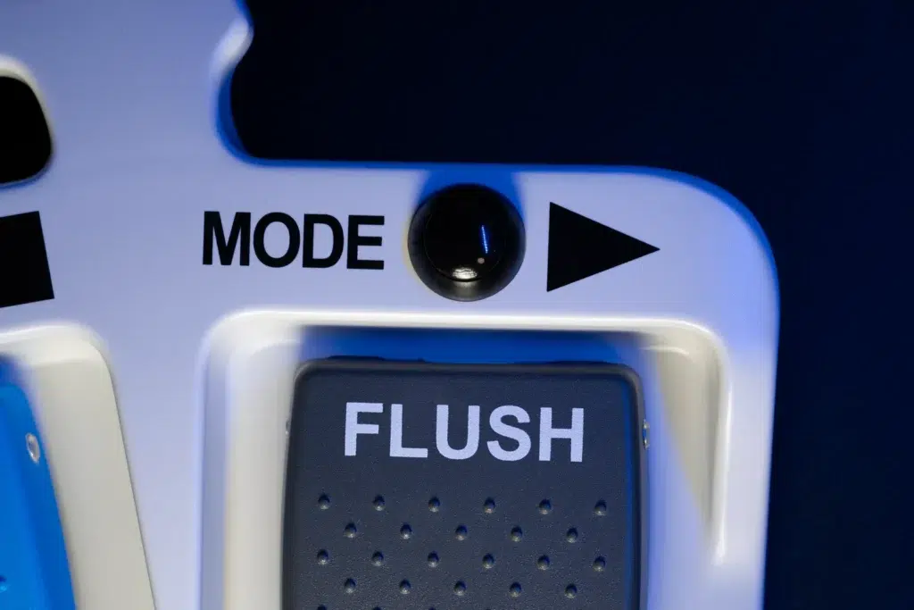
Safety Labeling Zones
Flat pad-print zones accept regulatory markings, warning text, and function identifiers. Medical-grade ink is validated against repeated chemical disinfection to keep safety labels legible throughout service life.
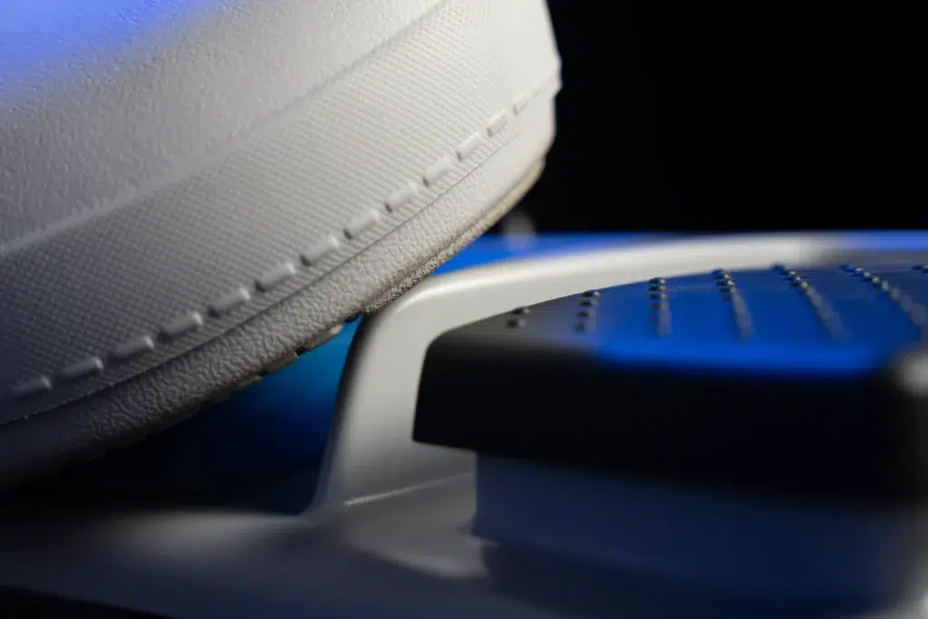
Tactile Treadle Divider
The raised center divider creates a distinct tactile boundary between adjacent pedals. Clinicians can locate and confirm pedal position by feel alone — preventing cross-activation of adjacent surgical functions.
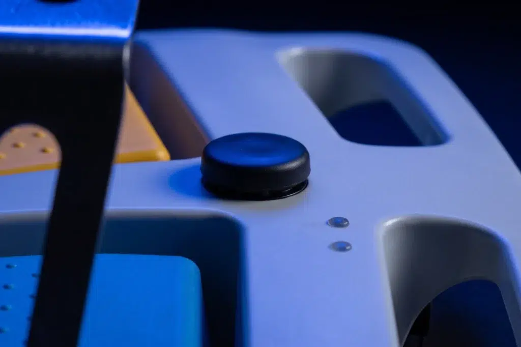
Button Activation Force
Multiple button styles and configurations are available to support different functions, tactile preferences, and workflow requirements. Customizable layouts help match actuation needs, control logic, and operator use across a wide range of applications.
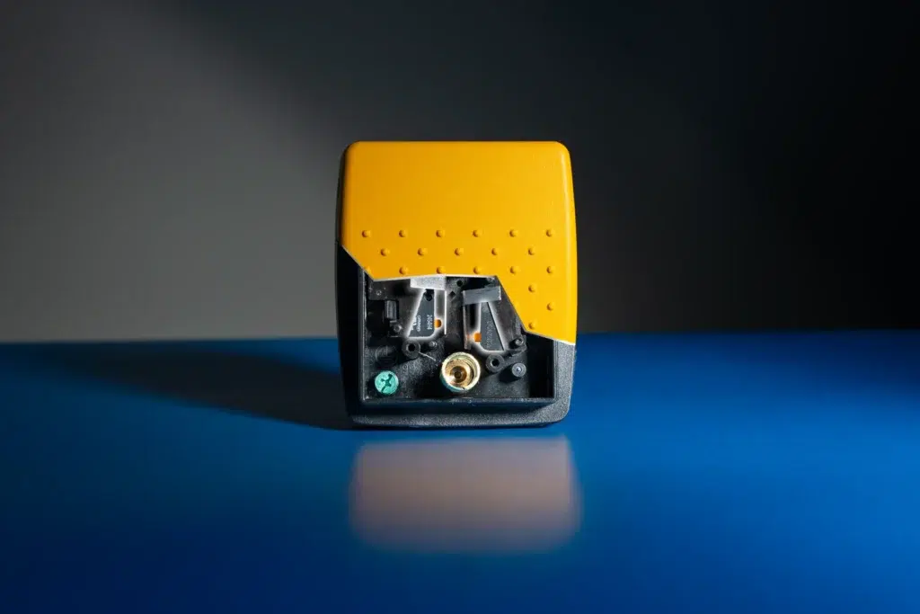
Two-Stage Actuation
Two-stage microswitch configurations arm equipment at ~30% pedal travel and activate at ~60%. This staged safety interlock is commonly used in laser systems, x-ray equipment, and ultrasonic aspiration devices.
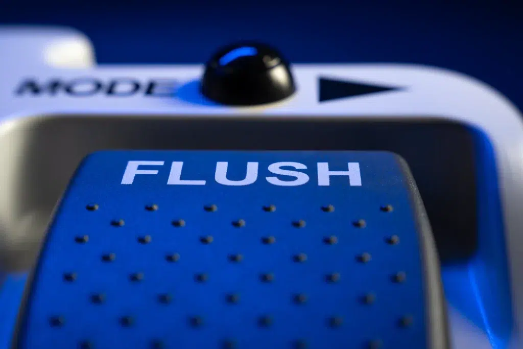
Function Labeling
Laser-engraved or pad-printed function labels (CUT / COAG / FLUSH) allow instant visual identification during procedures. Clear treadle marking is a primary defense against misactivation of the wrong surgical function.

Non-Slip Grip Surface
Integrated dimple texture provides traction in wet environments for shoe soles and surgical clogs. Optimized depth delivers grip without creating cleaning dead zones — maintaining hygienic safety under repeated disinfection.
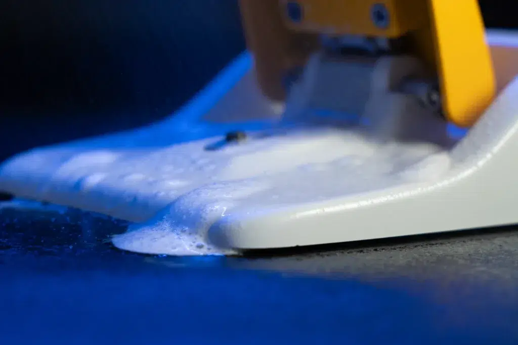
Fluid-Shedding Geometry
Sloped surfaces and radiused edges channel fluids away from seams and actuators rather than allowing pooling. The crevice-free housing supports thorough disinfection — validated against bleach, alcohol, and glutaraldehyde solutions.
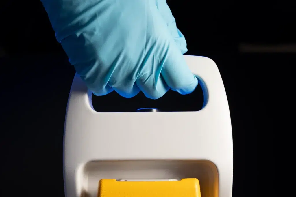
Handle
Integrated handles make our foot switches easier to carry, reposition, and transport between procedure rooms, carts, and storage areas.

Guards & Toe Loops
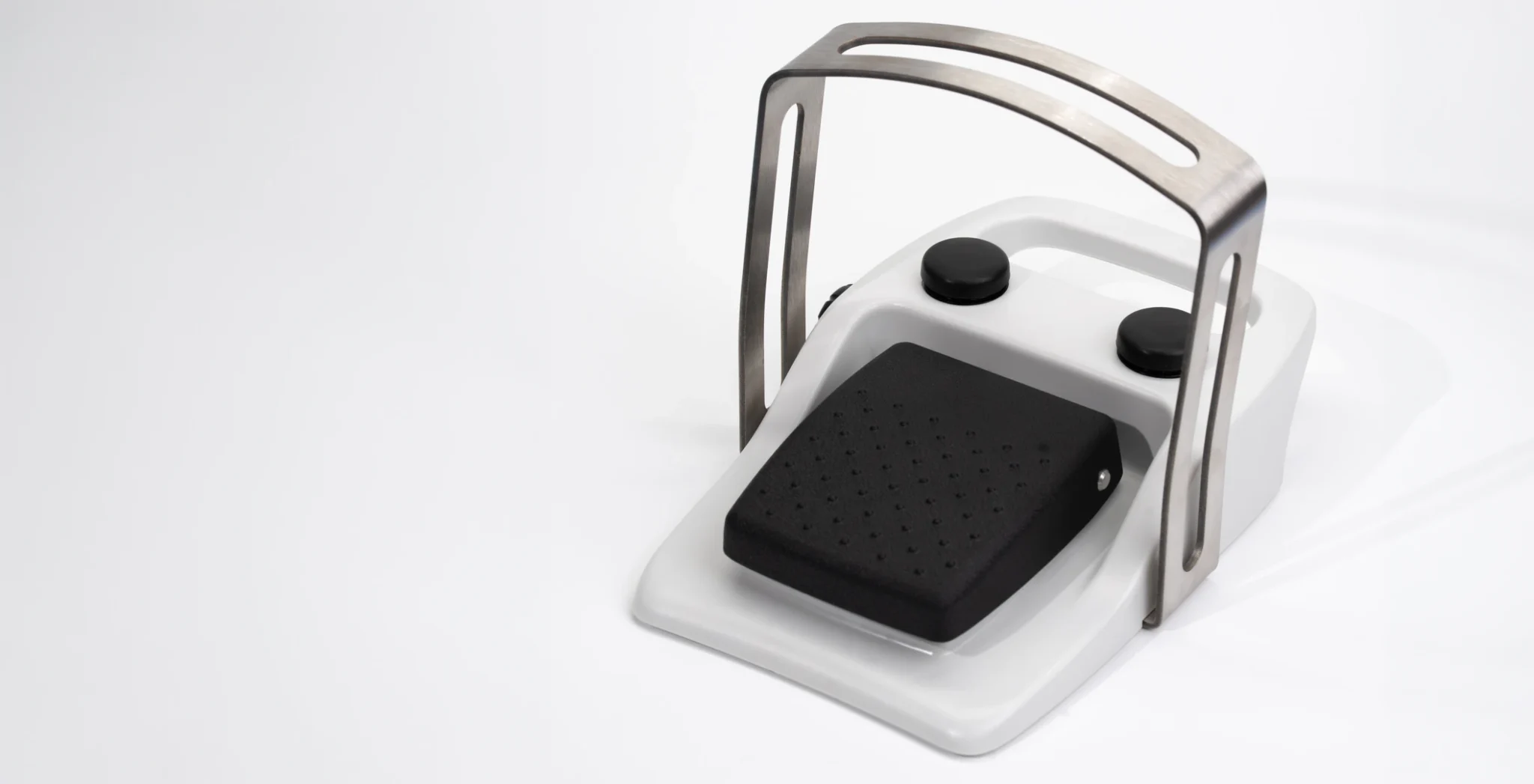
A guard typically becomes necessary when the foot switch controls something where an accidental press could cause harm. Many Class II and Class III surgical systems incorporate guarded foot switches as a standard risk control.
SAFETY ARCHITECTURE
How Risk is Engineered Out
Safety is not added at the end — it is the organizing principle behind every design decision, from sensor selection to fault response logic.
01
DFMEA-Driven Design
Every safety feature traces back to a Design Failure Modes and Effects Analysis. Potential failures are scored by severity, likelihood, and detectability, with the highest-risk scenarios driving redundancy and testing requirements.
02
Data Logging
Optional integrated data logging can capture serial numbers, current draw, pre-and-post travel settings, and testing report. Records can be stored in a central database if requested. Each device remains traceable by serial number throughout its service life.
03
Fault Reporting
When a fault is detected, the host console controls the response, sending an error signal, disabling switch output, or requiring a system reset. The foot switch operates within a broader system safety architecture.
04
200% Testing Capabilities
Every switch undergoes 200% testing, combining end-of-line testing with a full QC inspection, to ensure consistent performance and reliability before shipment.
PRODUCT GALLERY
Safety Engineering in Practice
Explore how safety principles are expressed across Linemaster foot control configurations, from single-pedal wireless units to multi-pedal surgical systems.

CLEANABILITY AS SAFETY
Designed to Be Cleaned
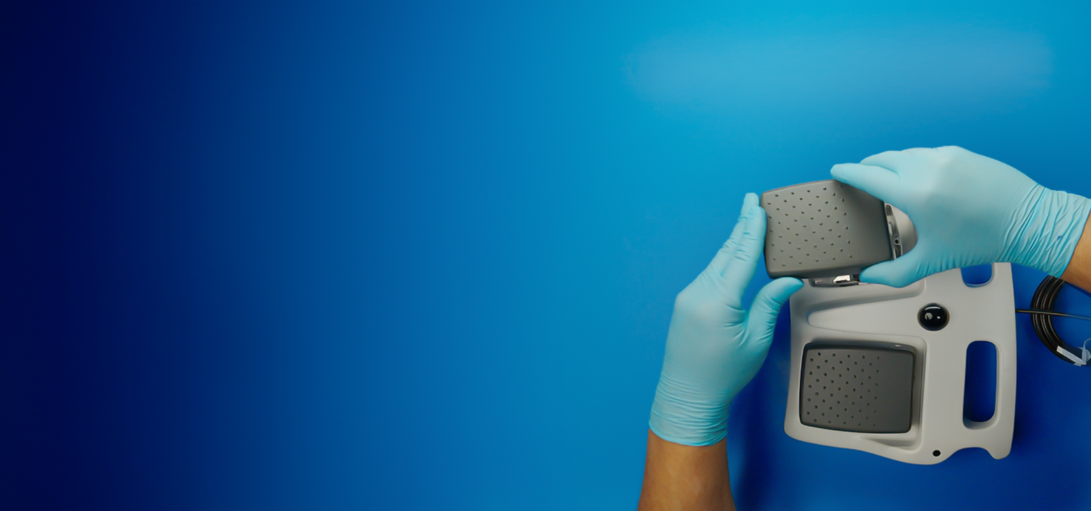
The flip-up treadle lifts clear of the housing so the surface underneath can be fully cleaned. Smooth transitions between surfaces let cleaning cloths move freely — no fibers caught in crevices, no fluid pooling near actuators.
SENSING TECHNOLOGY
Sensing Options & Their Safety Profiles
Sensor technology choice directly affects redundancy, wear characteristics, activation feedback, and the ability to detect faults in service.
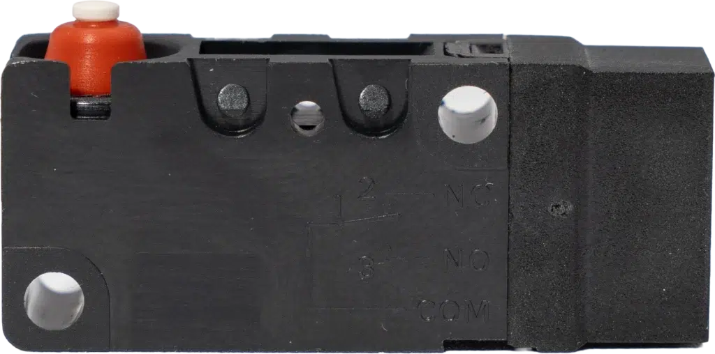
Microswitch Activation
Provides tactile and audible confirmation of activation preferred in some clinical environments.
- Tactile click confirms intentional activation
- Two-stage: arm at ~30%, activate at ~60% travel
- Used in laser, x-ray, and ultrasonic aspiration
- Adjustable trigger points
- Dual-switch redundancy available
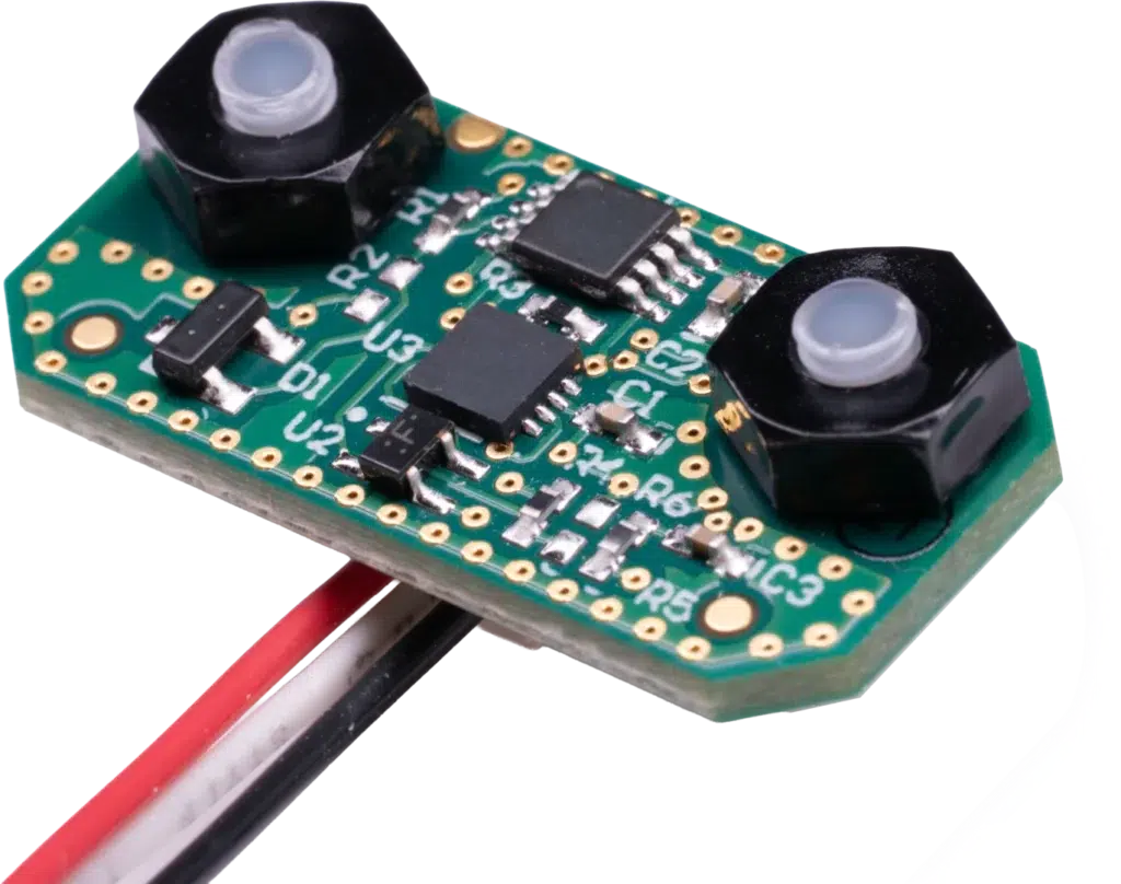
Hall Effect Sensing
Contactless technology eliminates mechanical wear at the sensing interface, enabling long-cycle reliability.
- Linear variable output for precision control
- No mechanical contact — no wear at sensing point
- Two-stage: arm at ~30%, activate at ~60% travel
- Adjustable activation
- Dual-sensor configuration with output comparison
- Fault flagged if sensor readings diverge
Tilt Detection
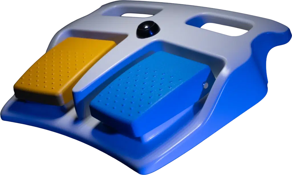
Orientation monitoring uses tilt detection and configurable actuation force to ensure the foot switch only responds to intentional input, automatically disabling all signals if the device is lifted, tipped, or moved out of position.
- Tilt detection disables all inputs if the device is lifted or tipped
- Uses an internal accelerometer to monitor the orientation of the foot switch during use
- Both safeguards ensure only intentional input triggers the switch
SAFETY COMPARISON
Safety Through Engineering
Each safety feature addresses a specific failure mode identified during risk analysis — here is how safety-engineered design differs from conventional foot switch design across key dimensions.
| Safety Dimension | Safety-Engineered |
|---|---|
| Sensing Redundancy | ✓Dual Hall sensors with continuous output comparison and fault flagging |
| Unintended Activation | ✓Configurable pre-travel dead band prevents rest-weight activation |
| Orientation Safety | ✓Accelerometer tilt detection automatically disables all inputs when lifted |
| Wireless Pairing | ✓NFC cradle + factory pre-pairing prevents adjacent OR cross-pairing |
| Battery / Power Failure | ✓LED or haptic low-battery alert; hybrid wired backup restores operation |
| Fluid Ingress | ✓IP68 buttons, conformal coating, crevice-free fluid-shedding geometry |
| Structural Validation | ✓Ball drop, crush, and impact testing repeated after chemical exposure |
| Cable Durability | ✓Flex, abrasion, anchor pull, and gurney rollover cycle testing |
VALIDATION TESTING
Validated to Perform. Tested to Fail Safely.
Safety features only have value if they perform under real-world conditions. Each validation protocol is designed to confirm that protection mechanisms remain effective throughout the device’s service life.
Mechanical Durability
Electrical & Wireless
Discuss Safety Requirements with Our Team
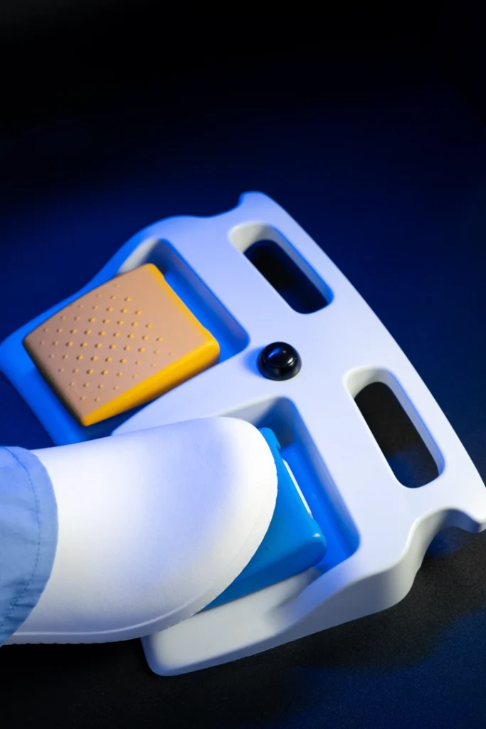
Whether you need redundant Hall effect sensing, a specific activation travel profile, or tilt-detection wireless operation, our engineers can help you map your safety requirements to the right Linemaster foot control.