
Medical Foot Switch Design, Testing,
and Manufacturing Capabilities
Linemaster Switch Corporation provides medical foot switch manufacturing capabilities that support OEM programs from initial application requirements through design, prototyping, verification support, production release, and ongoing supply.
Mechanical design, electrical architecture, actuation characteristics, cleanability, risk controls, manufacturability, and unit level traceability are evaluated as connected elements of the medical foot control program.
ISO 13485 Certified
Established in 1952
Working prototype in as little as two weeks
Production programs from approximately
100 to more than 100,000 units
Program Capabilities
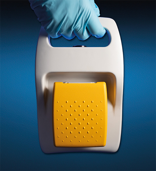
Medical foot controls can be developed for surgical systems, imaging equipment, diagnostic platforms, dental systems, surgical and medical tables, and other medical electrical equipment.
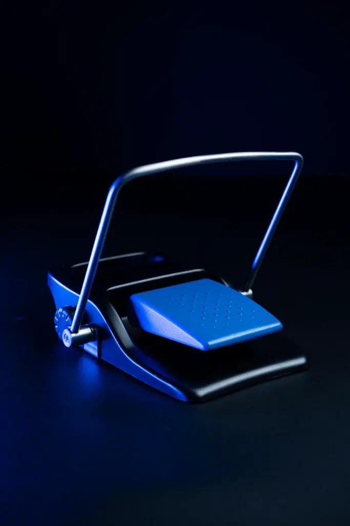
Engineering and Risk Controls for Medical Foot Switches
Medical foot control development combines solid modeling, rapid prototyping, additive manufacturing, risk analysis, and production engineering.
These capabilities allow mounting interfaces, pedal geometry, actuation characteristics, component placement, cable routing, sealing features, and mechanical relationships to be evaluated before production tooling is authorized.
DFMEA and PFMEA practices are incorporated to identify potential failure modes, establish appropriate controls, and inform design and process verification activities.
Mechanical Architecture
Housing geometry, treadle design, mounting interfaces, internal component placement, and cable routing are evaluated as part of the complete product architecture.
Actuation Characteristics
Pretravel, switching point, posttravel, operating force, and tactile response can be configured around the intended function and use environment.
Unintended Activation Controls
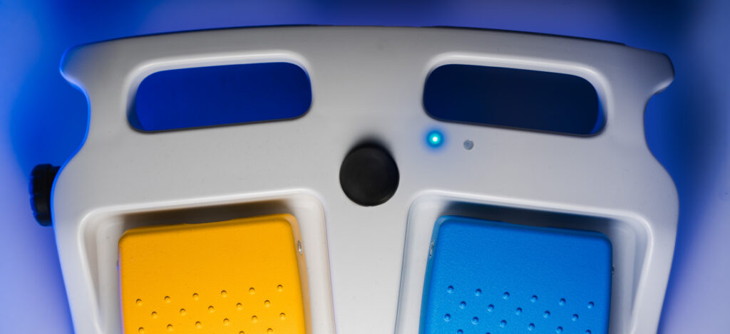
Guards, toe loops, pedal spacing, actuation force, pretravel, and orientation detection can be evaluated based on the system risk analysis.
Environmental and Mechanical Durability
Design evaluation can address repeated actuation, fluid exposure, cleaning agents, cable flexing, loading, impact, and cart or gurney rollover.
MECHANICAL DESIGN AND RISK CONTROL
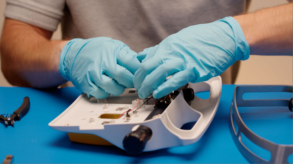
Rapid Prototyping
Additive manufacturing supports early evaluation of components that may ultimately be produced using different materials or manufacturing processes.
Brackets can be printed to evaluate fit, alignment, and mounting geometry before machined or production components are authorized. Housings, wiring channels, treadles, and molds for urethane casting can also be produced to support iterative evaluation.
This approach allows design changes to be assessed before permanent tooling or production processes are established.
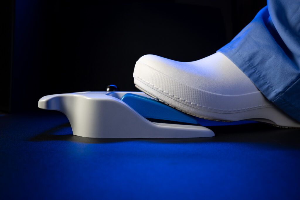
Actuation Travel
Actuation travel is treated as a functional design characteristic rather than an incidental mechanical dimension.
Controlled pretravel can reduce the potential for unintended activation when an operator rests a foot on the pedal. Posttravel contributes to the intended mechanical response after the switching point.
Travel, switching force, and tactile response are considered together because changes to one characteristic can affect the others.
Guarding and Orientation Detection
Guarding is evaluated based on the unintended activation risk associated with the specific application. It is not treated as a universal requirement for every foot control.
Tilt or orientation detection can provide an additional control by identifying when the foot control is no longer positioned as intended.
The appropriate combination of safeguards depends on the operating environment, system function, user interaction, and risk controls established for the complete medical device.
Wireless
Electrical, Electronic, and Wireless Foot Control Design
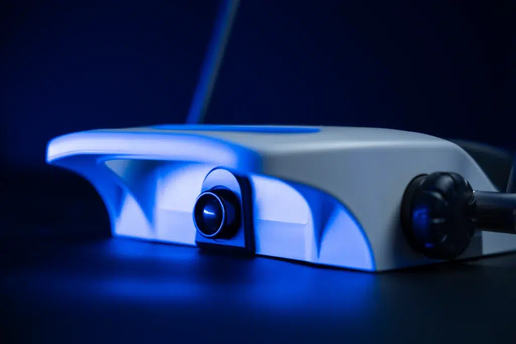
Electrical and electronic development is supported through Linemaster’s internal electronics laboratory, providing direct engineering oversight from circuit architecture and board layout through prototype evaluation and production implementation.
Design reviews can address circuit routing, component footprints, diagnostic functions, production test access, electrical isolation, fault detection, EMC considerations, and communication architecture.
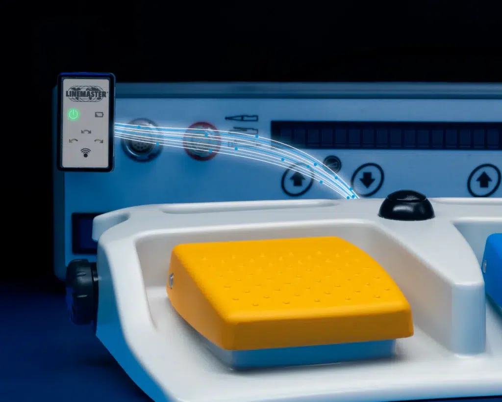
Medical foot controls can be configured for wired or wireless operation based on system requirements, operating conditions, communication needs, and risk analysis.
ELECTRICAL AND WIRELESS ENGINEERING DETAILS
PCBA Development
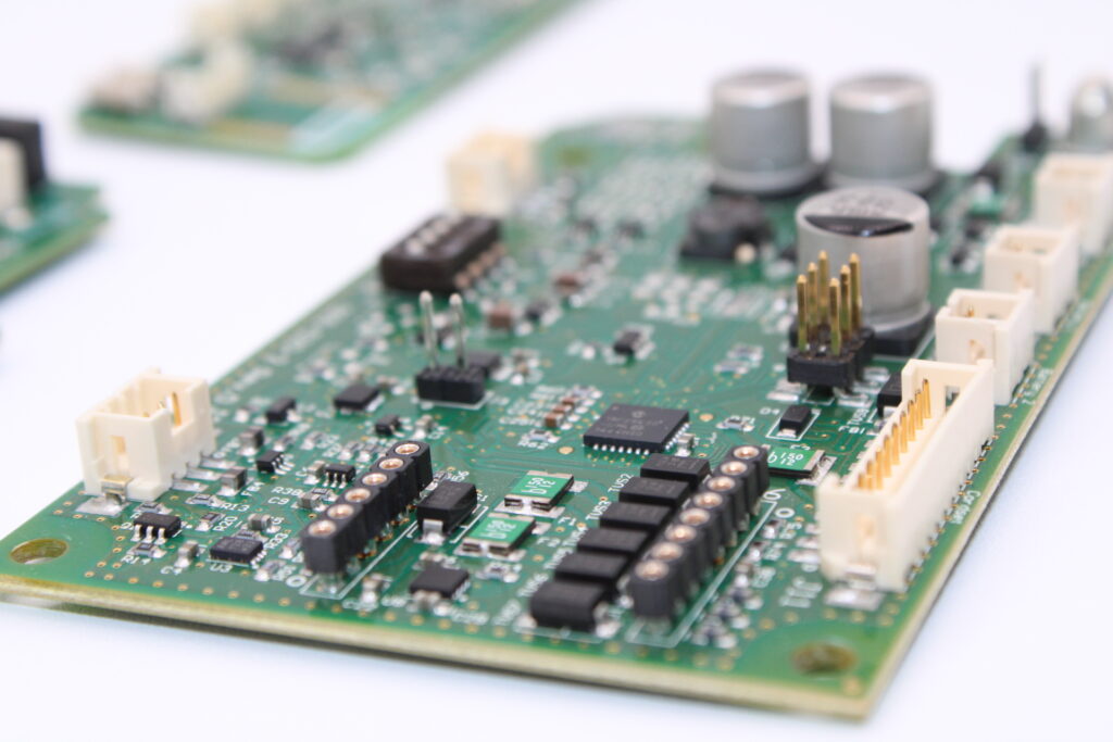
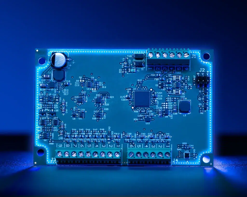
Circuit designs are developed using professional electronic design tools, commonly Altium.
Prototype assemblies can be populated and evaluated before production release. Test circuits may first be assembled on the bench to confirm the intended electrical behavior.
Diagnostic features and test points are incorporated where appropriate so that assembled boards can be evaluated during production, including through automated test methods.
Fault Detection
Sensing and response mechanisms can be incorporated for conditions that require detection.
Engineering activity focuses on identifying the applicable fault conditions, establishing the required response, and determining whether the output should be interrupted or placed into a defined safe state.
Electromagnetic Compatibility
A medical foot control may serve as a primary operator interface for an important system function.
Electromagnetic disturbance can contribute to interrupted communication, signal instability, or unintended system response. EMC is therefore addressed as both a functional performance and safety consideration.
Electrical Isolation
Design considerations can include circuit architecture, dielectric strength, interface conditions, potential fault paths, and the associated system risk controls.
Isolation architecture is established based on the interface requirements of the complete medical system.
Wireless Communication
Traditional radio frequency communication and Bluetooth Low Energy can be evaluated depending on the application.
Controlled pairing is particularly important in hospitals and procedural environments where multiple wireless systems may operate in close proximity.
Wired configurations retain a direct physical signal path. Wireless configurations remove cable related exposure to flexing, pulling, abrasion, rollover, and repeated cleaning.
The appropriate architecture is selected based on the complete system requirements rather than through a universal preference for either approach.
Wireless Development can address:
- Protocol Selection
- Signal Integrity
- Dropped Signal Management
- Controlled Pairing
- Prevention of Unintended Activation
- Communication Security
- Response following Communication Interruption
- Battery and Power Management
- Receiver Architecture
Testing
Medical Foot Switch Testing Before External Certification
Internal testing is used during product development and verification to evaluate performance, identify potential failure mechanisms, and reduce the likelihood of discovering design concerns during later external testing.
Linemaster is not an independent certified testing laboratory. Testing requiring specialized accredited laboratory capabilities or independent certification is performed externally.
Many internal methods are informed by applicable requirements of IEC 60601-1 and IEC 60529. The specific procedure, test parameters, sample size, and acceptance criteria depend on the product configuration and program requirements.
Internal testing capabilities include:
- Drop testing
- Impact testing
- Water immersion testing
- Force to activation measurement
- Mechanical life cycle testing
- Powered life cycle testing
- Crush testing
- Gurney rollover simulation
- Cable bend testing
- Cable pull testing
- Dielectric strength testing
View Test Methods and
External Laboratory Scope
Drop Testing
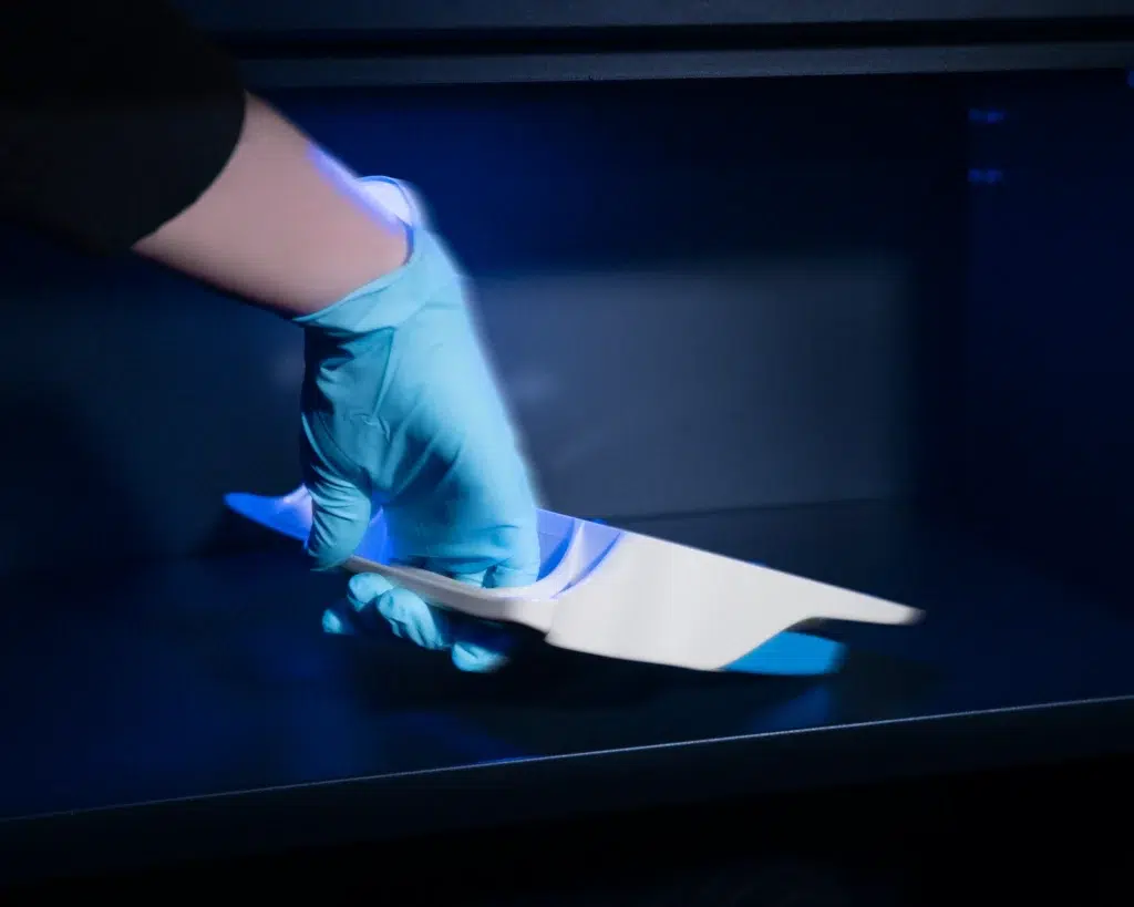
Units can be dropped from defined heights, including one meter, onto a hard surface.
Testing can include multiple orientations such as flat surfaces, corners, and edges. Following testing, the product is inspected for mechanical damage and evaluated to determine whether actuation remains within specification.

Impact Testing
A controlled impact method uses a steel ball measuring 50 millimeters in diameter.
The ball is released from a height of 1.3 meters through a guide tube onto a defined location on the pedal. The guide controls the impact location and supports repeatability between test units.
The product is then inspected for housing cracks, internal deformation, or other evidence of damage.

Cleaning Agent Compatibility
Applicable product configurations can be evaluated using cleaning agents and disinfectants representative of the intended medical environment.
Evaluated substances can include:
- CaviCide
- Cidex
- Enzol
- Bleach solutions
- Saline
- Soap solutions
- Isopropyl alcohol
The evaluation considers whether repeated exposure contributes to cracking, degradation, swelling, loss of mechanical properties, or other material changes.
The selected agents, concentrations, contact times, and number of exposures should be based on the intended cleaning process.

Life Cycle and Cable Testing
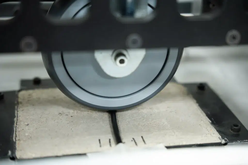
Mechanical cycling, powered cycling, and cable bend testing are performed using purpose built equipment within Linemaster’s testing and development operations.
Test equipment can include force measurement systems, mechanical cycle actuators, and sealed immersion tanks.
External Laboratory Activities
External testing can include:
- EMI and RFI testing
- ESD testing
- Extended immersion
- Agency certification
- High pressure washdown evaluation
- Applicable product safety testing
External reports and certifications can support the medical device manufacturer’s regulatory submission and technical documentation, as applicable.
UL manages listing activities for applicable Linemaster stock products. A custom configuration derived from a listed platform may be able to use portions of the existing certification basis, subject to the nature of the modification and agency determination.
Water Immersion Testing
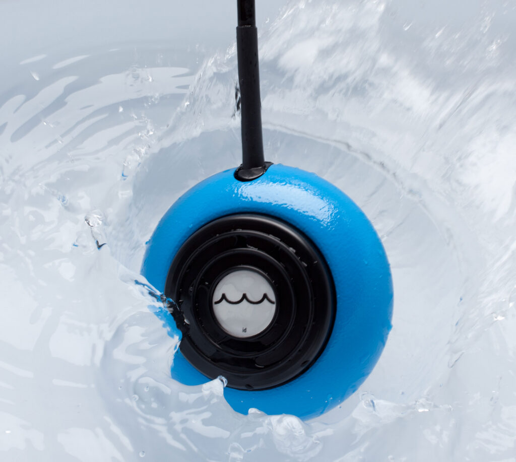
One internal method places the foot control beneath 250 millimeters of saline water for one minute while the pedal is activated 50 times.
A separate deep tank method holds the unit at a depth of 1.2 meters for 24 hours before electrical evaluation.
Following exposure, the unit is opened and inspected for evidence of liquid ingress around contacts, interfaces, and internal cavities. Dielectric strength testing is then performed to evaluate insulation integrity.
These methods evaluate immersion conditions. They are not represented as splash, rain, spray, or high pressure washdown evaluations.
Review Your Medical Foot Control Requirements
Discuss the intended function, interface requirements, operating environment, expected volume, and verification needs with Linemaster’s engineering and applications teams.
Tooling
Qualified Tooling and Controlled Production
Repeatable medical foot switch manufacturing depends on controlled equipment, qualified tooling, documented assembly methods, and consistent inspection criteria.
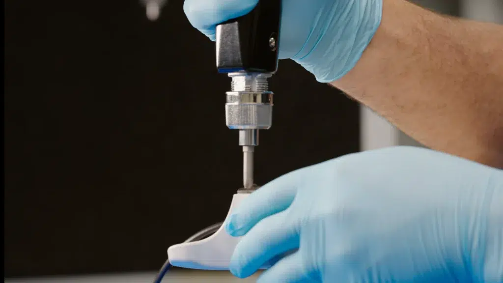
Custom jigs and fixtures are used where product specific control of orientation, alignment, torque, insertion force, potting, machining, staking, or component placement is required.
Fixtures are qualified before routine production use and maintained under defined Preventive Maintenance programs.
MANUFACTURING FIXTURE AND PROCESS CONTROLS
Assembly Positioning Fixtures
Assembly positioning fixtures hold switches, housings, and subassemblies in a defined orientation during assembly.
The fixtures support repeatable component alignment and allow the operator to complete the process without manually maintaining the position of the assembly.
Qualification and Maintenance
Custom fixtures undergo Installation Qualification and Operational Qualification before production release.
Defined Preventive Maintenance activities can include:
- Routine inspection
- Functional evaluation
- Wear assessment
- Adjustment
- Component replacement
Engineering, Manufacturing, and Quality personnel participate in tooling development and qualification so that the production method remains aligned with the product requirements and inspection controls.
Torque Fixtures
Torque fixtures are used where switches, connectors, or other components must be tightened to a specified value.
The fixture maintains alignment, limits movement during tightening, and reduces the potential for component damage.
Label Placement Fixtures
Label placement fixtures control label position and orientation.
Consistent placement supports product identification, traceability, and applicable labeling requirements. Label printing is also performed internally, allowing controlled revisions to be implemented efficiently.
Spring Loading and Snap Fit Fixtures
Dedicated fixtures are used for assemblies that require controlled alignment or insertion force.
Separate fixtures can also be used to disassemble snap fit components during inspection, validation, repair, or rework.
Machining Fixtures
Machining fixtures hold components during drilling, milling, and tapping.
These fixtures support dimensional consistency, reduce setup variation, and allow prototype and production components to be manufactured to defined tolerances.
Potting Fixtures
Potting fixtures maintain the position of the assembly while epoxy is applied and cured.
Controlled fixturing supports repeatable epoxy placement and helps protect internal components from moisture, vibration, and contaminants.
Staking Fixtures
Staking fixtures control the localized deformation of metal components used to retain parts permanently.
The fixture maintains component alignment, controls the location of the staking operation, and protects adjacent components.
Regulatory Support
Unit Level Traceability, Documentation, and Regulatory Support
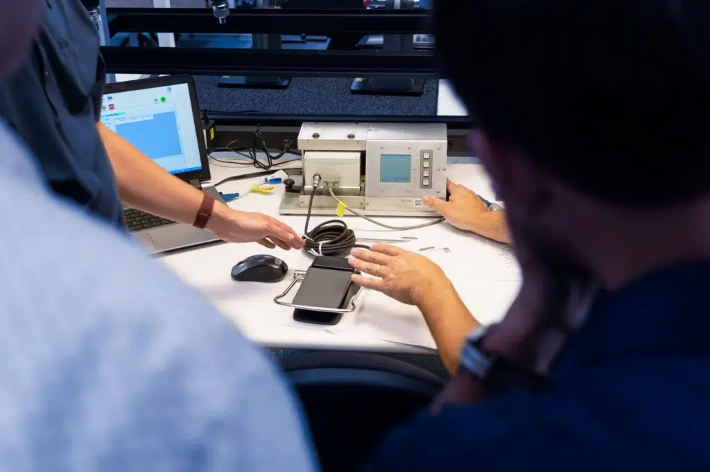
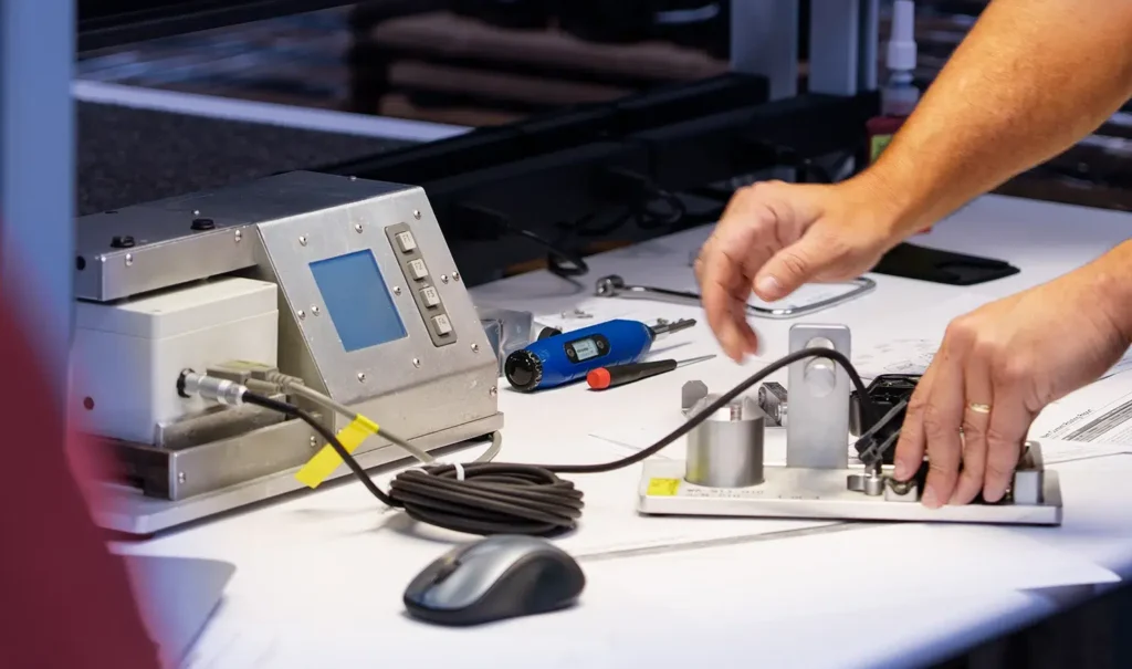
Applicable production programs can record defined performance values for each unit and retain those records in a searchable database.
Unit level records provide objective evidence of manufacturing performance and allow historical production information to be reviewed in support of audits, investigations, calibration analysis, and manufacturing trend evaluation.
Documentation is developed throughout the program and aligned with the released product configuration, rather than assembled only after design completion.
Regulatory Status of the Foot Control
Regulatory treatment depends on intended purpose, labeling, configuration, jurisdiction, and how the product is placed on the market.
A medical foot control may be evaluated as a component within a finished medical device. In other circumstances, it may meet the applicable definition of a medical device accessory and be subject to separate requirements.
Linemaster provides applicable design, verification, manufacturing, and traceability documentation to support the OEM’s regulatory assessment and device level submission activities.
The medical device manufacturer remains responsible for determining the regulatory status of the finished device and its accessories.
Quality and Compliance Considerations
Applicable FDA requirements, EU MDR requirements, ISO 13485 controls, UL standards, RoHS restrictions, and REACH obligations can influence product documentation and manufacturing activities.
Linemaster maintains ISO 13485 certification for the design, manufacture, testing, and servicing of catalog and custom foot switches for medical applications.
Where safety agency approval is required, Linemaster can support the submission process subject to the product configuration, agency scope, and program requirements.
Production Data Logging
Production data logging can record defined functional or calibration values for every applicable unit.
For one program, the production system recorded:
- Minimum travel
- Maximum travel
- Raw output value before linearization
Several years later, the retained records allowed the customer to evaluate historical calibration performance against defined tolerance criteria.
Because the values had been recorded for each unit, the production population could be evaluated directly rather than reconstructed from limited sample data.
Documentation Support
Applicable documentation can support:
- OEM product release
- Design verification activities
- Incoming inspection requirements
- Device history or production record needs
- Regulatory submissions
- Technical documentation
- Audit requests
- Investigation activities
- Product identification and traceability
Product and shipping carton labels can be configured to meet specified identification requirements. Internal label printing allows revisions to be implemented through a controlled process.
Custom Configurations
Custom Medical Foot Control Configurations
Standard Linemaster platforms can provide an efficient starting point for development time, program cost, component availability, and verification planning.
When an existing platform does not satisfy the application requirements, the medical foot control can be configured around the mechanical, electrical, environmental, ergonomic, and functional requirements of the complete system.
The extent of the departure from a standard platform influences development cost, verification scope, documentation requirements, tooling, and production implementation.
Limited changes may be supported by existing design and verification evidence, subject to technical review.
More extensive modifications are managed as custom programs with separate requirements, quotation, documentation, and verification activities.
Available configurations can include:
- SPST, SPDT, DPST, and DPDT switching
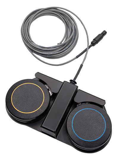
- Single, dual, or triple pedal arrangements
- Variable or discrete output
- Redundant mechanical or electrical functions
- Guards and toe loops
- LED indicators
- Custom labeling and identification
- Wired or wireless communication
- Custom cord sets and connectors
View Additional Configuration Options
Additional options can include:
- Alternative treadle force
- Modified pretravel and posttravel
- Custom treadle geometry
- Custom housing geometry
- Custom decals
- Packaging configurations
- Application specific ingress protection requirements
- Battery tube configurations
- Standard or custom buttons
- Wireless receiver configurations
- Custom colors
- Product artwork
- Material changes

Why Organizational Continuity Matters
The same organization that supports development also carries the product into production.
This continuity helps preserve:
- Design intent
- Requirements history
- Risk control decisions
- Manufacturing knowledge
- Tooling rationale
- Inspection requirements
- Product specific process knowledge
Experience gained from manufacturing millions of switches for medical, laboratory, and industrial environments also provides practical knowledge of mechanical, electrical, environmental, and manufacturing failure mechanisms.
That knowledge can be applied during new product development to reduce avoidable design changes, support design transfer, and provide a more controlled path from concept through production release.
Integrated Medical Foot Control Operations in Connecticut
Linemaster’s Connecticut operations integrate product development, electronic design, prototyping, testing, machining, production assembly, cable assembly, warehousing, and final inspection within one organization.
Core design, production, assembly, and final inspection activities are centered in Woodstock, Connecticut. Warehouse and cable assembly operations are located in Plainfield, Connecticut.
This organizational continuity allows product requirements to be evaluated with materials, tooling, tolerances, component availability, assembly methods, sealing processes, cable construction, inspection, and serviceability considered throughout the program.
Linemaster Switch Corporation was formally established in 1952, with its foundation dating to 1937.
Discuss Your Medical Foot Control Application
Share the intended function, system interface, operating environment, expected annual volume,
and target program timing.
Linemaster’s engineering and applications teams can review whether an existing platform, configured platform, or fully custom medical foot control is appropriate for the program.
FAQ’s
What capabilities should a medical foot switch manufacturer provide?
A medical foot switch manufacturer should be able to support requirements review, mechanical and electrical design, prototype development, risk analysis, verification testing, qualified production tooling, manufacturing controls, documentation, and production traceability.
The specific scope depends on the intended function of the foot control and the requirements of the complete medical device.
Can Linemaster design a custom medical foot control?
Yes. Linemaster can begin with an existing platform, configure a standard design, or develop a more extensive custom foot control.
Options can include switching architecture, pedal count, actuation force, travel, wired or wireless communication, housing design, cord sets, connectors, indicators, labeling, and safety related features.
How long does it take to obtain a custom medical foot switch prototype?
A working prototype can be available in as little as two weeks.
Actual timing depends on the design scope, component availability, custom materials, electronic content, and the completeness of the application requirements.
How is consistency maintained across production volumes?
Consistency is supported through qualified fixtures, defined assembly processes, controlled torque and placement, tooling qualification, Preventive Maintenance, inspection controls, and applicable unit level data logging.
Production requirements are established against the released configuration and maintained through documented manufacturing controls.
What medical foot switch testing does Linemaster perform internally?
Internal capabilities include drop, impact, immersion, activation force, mechanical life cycle, powered life cycle, crush, rollover, cable bend, cable pull, and dielectric strength testing.
The applicable methods and acceptance criteria are established based on the product configuration and program requirements.
Which tests require an external laboratory?
External activities can include EMI and RFI testing, ESD testing, extended immersion, high pressure washdown evaluation, applicable product safety testing, and independent certification.
External reports can support the medical device manufacturer’s technical documentation and regulatory submission, as applicable.
How is water resistance evaluated?
Internal methods can include controlled saline immersion and extended depth exposure followed by internal inspection and dielectric strength evaluation.
The test method should be selected based on the expected exposure and the applicable ingress protection requirements.
Does Linemaster provide documentation for regulatory submissions?
Linemaster can provide applicable product specifications, verification information, manufacturing records, traceability data, and labeling information to support OEM regulatory activities.
The exact documentation package depends on the product configuration, program requirements, and the regulatory status of the foot control within the complete system.