
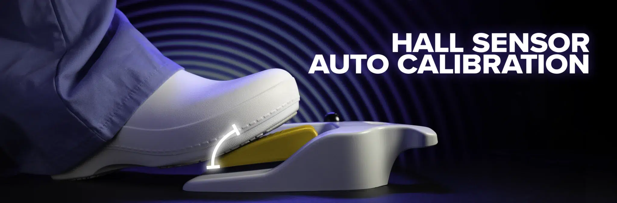
Auto Calibration of a Hall Sensor in Foot Switches: What It Does and Why It Matters
A Hall sensor based foot switch looks like any other from the outside. Press the pedal, get an output. But inside, before the output means anything to the equipment, the raw sensor reading has to be translated into something the system can act on. That process is calibration. On every modern Linemaster design, it runs automatically.
Here is a closer look at how auto calibration of a Hall sensor works inside a foot switch, when it runs, and why it has become a baseline expectation rather than an optional feature.
What Auto Calibration Does
A Hall sensor doesn’t report absolute values. It reports a raw signal that depends on its distance from a magnet, the strength of the field at that point, and a handful of mechanical and electrical variables. Without something to translate that raw signal into known reference points, the system has no way of knowing what the sensor’s reading at rest means, or what it’s reading at full press means.
Calibration is what closes that gap. It maps the raw sensor output to expected values the system can actually use. The cleanest way to picture it is the tare function on a weight scale. The scale already has the weight of its own platform pressing on the sensor, plus whatever bias and offset the internal components introduce. When you tare it, you tell the system that whatever it is reading right now should count as zero. Anything heavier than that baseline reads as actual weight. Hall sensor calibration in a foot switch works on the same principle. The pedal at rest produces a raw value that isn’t zero. The pedal fully pressed produces a raw value that isn’t the maximum. Calibration sets the reference points so the system knows what zero and full really are.
Auto calibration is the same process, automated. Instead of an operator entering reference values or zeroing them out by hand, the firmware handles it. The result is the same mapping, without the manual labor or the human error.
When Auto Calibration Runs
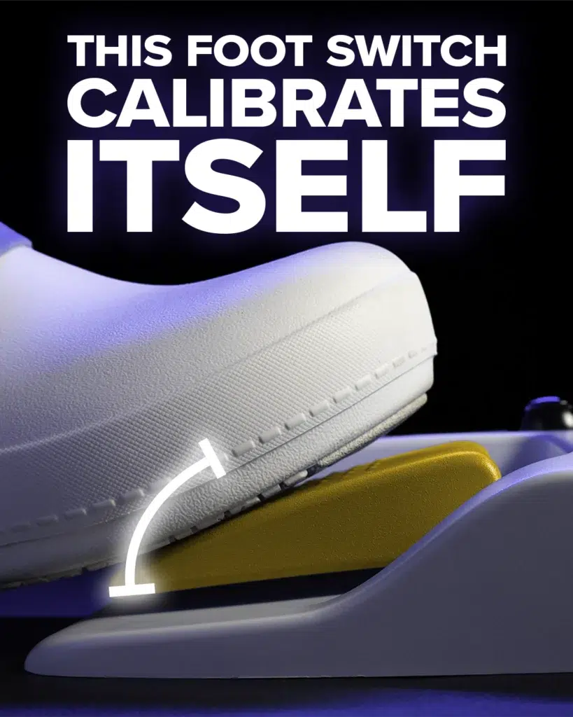
Auto calibration doesn’t run on every power up. It runs by command, whenever something changes the physical stack up between the magnets and the Hall sensor.
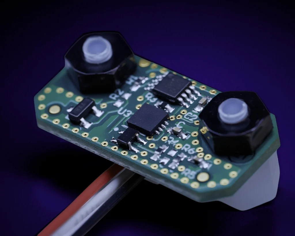
The list of changes that matter is shorter than it sounds. Swapping the screw that holds a magnet. Shifting a pedal. Removing and reinstalling a board. Replacing a component during service. Each of those can move the magnet relative to the sensor by enough to throw the previous calibration off. The board can go back in the same spot it came out of and still land at a slightly different angle.
This matters most in the field. Any time a switch is physically opened during repair or component replacement, calibration needs to run again before it goes back into service. During normal production where nothing has shifted, recalibration isn’t needed. The rule is straightforward. If the physical relationship between the magnet and the sensor was changed, recalibrate.
What Happens During an Auto Calibration Cycle
When auto calibration runs, the firmware is looking for two things. The minimum raw value at the resting position and the maximum raw value at full press. The operator presses the pedal between those two positions, and the circuit captures the readings at both ends. To make sure the average is reliable, the firmware records the minimum and maximum across three full presses each. A press that doesn’t reach the bottom or doesn’t fully return to rest gets averaged out by others.
Once those reference points are locked in, the firmware imposes a linear range between them. If the raw values come in between 10 and 90 but the system is supposed to output between 0 and 100, the firmware subtracts the offset at the bottom and adds the headroom at the top, then scales everything in between proportionally. The result is a clean linear response across the full travel of the pedal.
That is the core of the calibration cycle. Three presses of the pedal, half a second each, and the sensor is mapped.
Linear, Exponential, and Anything In Between
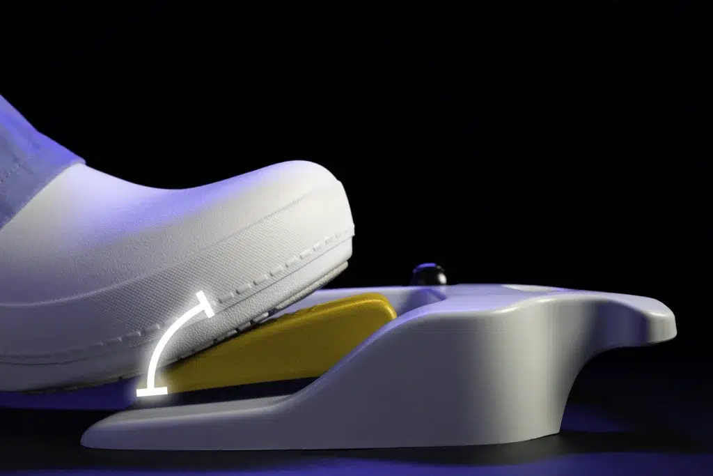
With a known minimum and maximum on the table, the firmware doesn’t have to stop at a linear response. It can apply different response profiles depending on the application.
An exponential curve gives very small output changes at the beginning of the pedal travel and ramps up quickly toward the end. That suits applications like fine cutting or sculpting, where the operator wants precise control during slow movements and aggressive output during full press. The opposite curve, where most of the output sits at the start of the travel and tapers as the pedal approaches the bottom, supports applications that need a fast initial response and a smoother finish. Any response shape the application calls for can be implemented once the sensor is calibrated.
This the part of auto calibration that tends to get overlooked. Calibration isn’t just about getting accurate readings. It is also the layer that makes response shaping possible at all.
What Goes Wrong Without Auto Calibration
Without calibration, a foot switch ships with whatever performance the mechanical stack up happens to produce. Some units come out accurate. Others land loose. Some come up short on pre-travel. Others come up short on post-travel. Each of those translates into a different problem for the operator.
Too little pre-travel is the most serious of the bunch. If the pedal at rest is already reporting a small output instead of a true zero, the equipment it controls can start moving on its own, without any input from the operator. That is what inadvertent activation looks like in practice, and in a medical foot switch it is exactly the failure mode the rest of the design exists to prevent. Too little post-travel creates the inverse problem. The operator presses the pedal all the way down and the equipment never reaches full output, because the calibration is reading short of the actual maximum.
The reason any of this is an issue comes back to the magnets themselves. No two magnetic fields are shaped exactly alike. The differences are small, but they add up across the magnet, the mounting hardware, the board position, and the sensor itself. Even Hall sensors that are laser calibrated at the factory can’t fully account for that variation. Auto calibration is what neutralizes it.
The Misconception Worth Clearing Up
Most engineers already know what calibration means. The misconception isn’t about the concept. It is about the assumption that the magnets going into a foot switch are identical from unit to unit and from lot to lot.
They aren’t. Magnetic fields vary in shape and intensity, even between magnets that come off the same line. That variability is what makes calibration necessary in the first place. Skip it, and the same design starts producing different results depending on which magnet happened to land in which assembly.
Auto vs. Manual, on the Floor
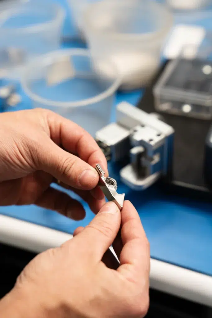
The difference between auto and manual calibration shows up clearly on the production floor. Manual calibration requires an operator to press the pedal down, turn a potentiometer to zero out the value at rest, and then repeat the process at the maximum position. The work has to be exact. A single pedal takes close to a minute. A triple pedal takes three. Human factors creep in along the way. A small inconsistency or a moment of fatigue is enough for an operator to overcompensate or undercompensate by just enough to push the calibration outside its window.
Auto calibration runs in a small fraction of that time. Three presses of the pedal at roughly half a second each finishes the cycle on a single pedal, and a triple pedal is finished in seconds rather than minutes. The firmware handles the precision at a level the operator could never match by hand.
Where Auto Calibration Earns Its Keep
Medical applications get the most out of auto calibration. The output of a medical foot switch has to be repeatable and reliable across the production run, with no room for the kind of unit-to-unit variation that uncalibrated mechanical stack ups produce. Auto calibration is what makes that consistency economically viable at the volumes medical OEMs need.
Temperature is a secondary factor on some sensor designs, but it doesn’t drive calibration decisions on Linemaster foot switches. The Hall sensors used in these designs have a flat temperature curve, which means the reading doesn’t drift meaningfully with hot or cold conditions. The mechanical tolerances and magnetic fields are where the real variation lives, and calibration is what takes those out of the equation.
Linemaster moved away from manual calibration on new designs more than fifteen years ago. Every Hall sensor foot switch platform built since then handles calibration in firmware as part of the standard design.
Looking Ahead
Auto calibration is one of those design areas where the value isn’t always obvious until you look at what the alternative actually costs. Manual labor on the production floor, inconsistent performance unit to unit, restricted field service, and a hard ceiling on what response curves the equipment can use. None of those problems an OEM wants to inherit on a new design.
If you are evaluating a Hall sensor foot switch for a medical, industrial, or laboratory application, calibration is one of the conversations worth having early. It shapes the response curve, the field serviceability, and the unit-to-unit consistency long before the first prototype ships. If that sounds like the stage you are at, our engineering team is always open to a conversation about what the calibration approach should look like for your application. Reach out through the contact page and we can take it from there.
Meet The Author

Arijan Kandic
Digital Marketing Specialist
Arijan is the Digital Marketing Specialist at Linemaster Switch Corporation and holds a bachelor’s degree in business management from Quinnipiac University. He manages the company’s SEO strategy, Google Ads campaigns, and digital marketing initiatives, and develops educational content for the Linemaster Learning Center to help engineers, OEMs, and medical device manufacturers better understand foot switch technology. Arijan works closely with Linemaster’s engineering and applications teams to translate complex technical concepts into clear, accurate articles on foot switch design, customization, and compliance considerations.
In Collaboration with

William Chan
Chief Electrical Design Engineer
Bill has more than thirty four years of experience in high speed digital and analog electronic system architecture and hardware circuit design across the medical and security industries. He has been with Linemaster for over sixteen years and serves as the primary technical contact for customer electrical requirements and application specific solutions. He is best known for his wired and wireless low power digital and analog circuit designs, PCBA development, and cybersecurity focused hardware work.
Uploaded 09/15/2026
Custom Foot Switches
Linemaster’s custom footswitches are designed to meet specific user requirements, offering a range of features such as various pedal configurations, wired and wireless options, and customizable LED indicators. These custom footswitches provide reliable, durable solutions tailored to enhance functionality in diverse applications.

