
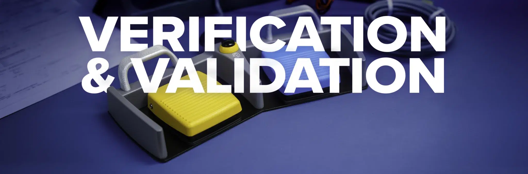
Verification and Validation Units: Why Build Equivalence Determines Whether the Evidence Holds
Verification and validation activities generate evidence about the units that are tested. Whether that evidence accurately represents the product that will ultimately be supplied depends on how closely those units reflect the intended production configuration.
This concept is often described as production representativeness or build equivalence.
Build equivalence does not necessarily mean that every verification unit must be produced using the final production equipment. Instead, the manufacturing characteristics that could influence the requirement being evaluated should be representative of the intended production process, or differences should be identified and technically justified.
This distinction is important. A prototype may be appropriate for evaluating one design requirement while being unsuitable for another. The determining question is whether differences in equipment, process, material condition, or assembly method could influence the test result.
For final validation activities, production representative units become particularly important because the objective is to demonstrate that the final product performs as intended under defined conditions of use.
What Build Equivalence Requires
Component identity alone does not establish build equivalence.
Two units built from the same bill of material can differ in ways that influence verification or validation results when their manufacturing methods differ.
Production representativeness should be considered across three primary areas.
Equipment and Tooling
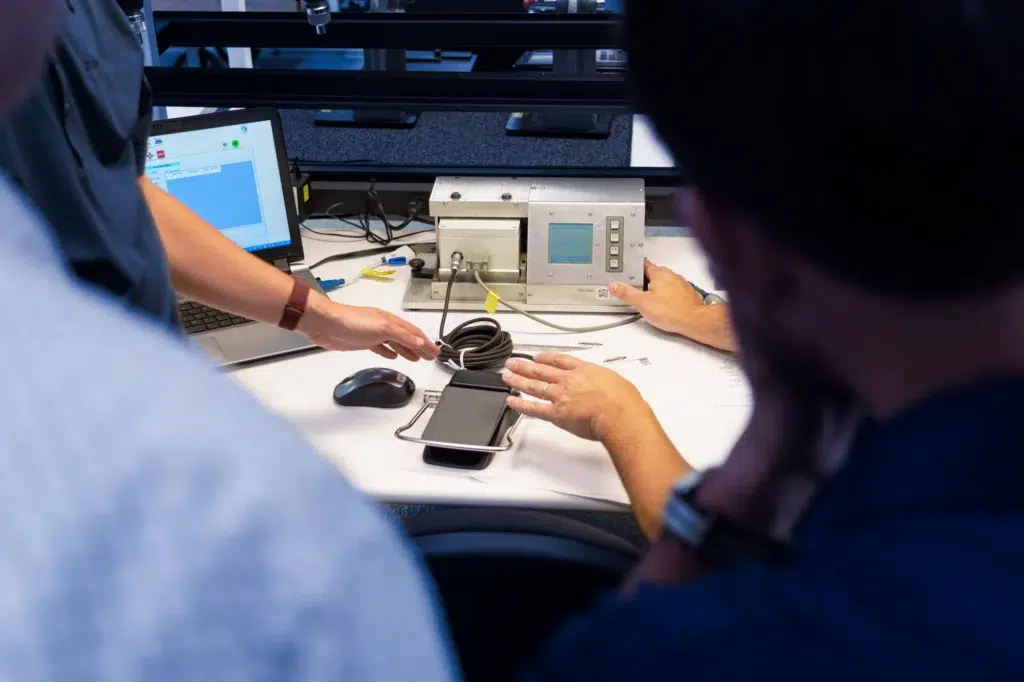
Tooling, fixtures, machinery, and production equipment can influence dimensional consistency, surface condition, residual stress, component placement, and tolerance distribution.
A component produced using development equipment may therefore behave differently from the same design produced using the intended production process.
Whether that difference matters depends on the requirement being evaluated.
For example, a machined housing produced from the specified material may be acceptable for evaluating some dimensional or interface requirements. The same housing may be less representative for evaluating characteristics affected by molding conditions, such as residual stress, environmental stress cracking, or long term chemical compatibility.
Manufacturing Processes
Manufacturing processes include the defined sequence, parameters, materials, and controls used to produce the product.
Where the test result depends on these characteristics, the process used to produce the test units should represent the intended production method or the difference should be evaluated and justified.
Assembly Methods
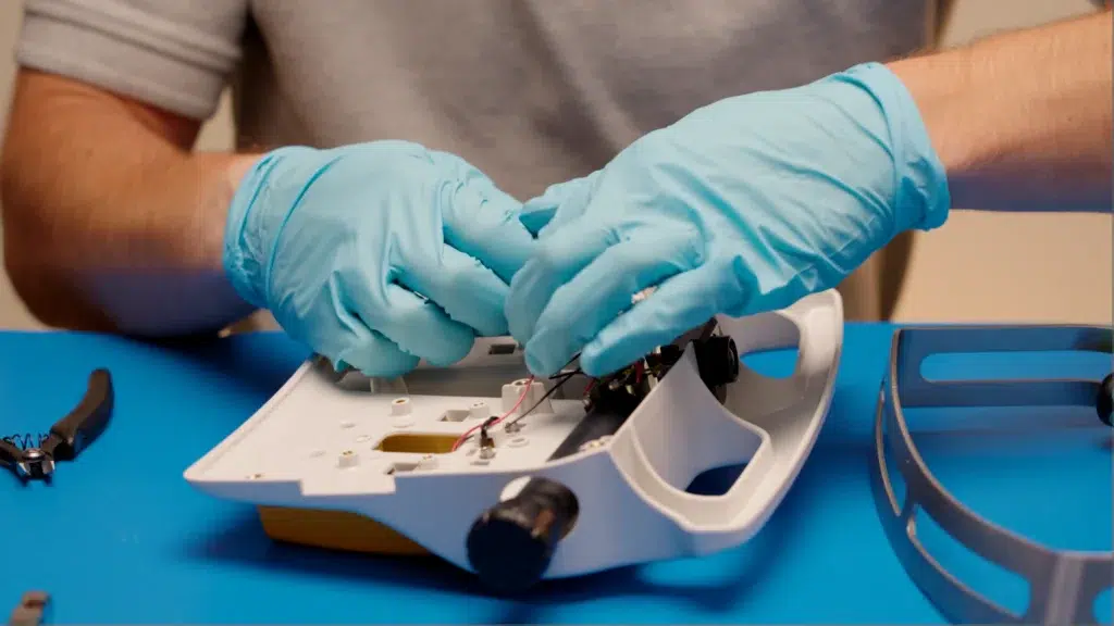
Assembly techniques, work instructions, fixtures, operator controls, and inspection methods can influence the distribution of performance in an electromechanical product.
A highly controlled engineering prototype build may receive individual attention that will not exist during routine production. While this can result in a well performing prototype, it may not accurately represent the variation expected within the production population.
For verification and validation activities that depend on assembly controlled characteristics, this difference becomes important.
Operations such as:
- Potting
- Adhesive application
- Sealing
- Fastener torque
- Staking
- Cable termination
- Soldering
- Component positioning
- Cure processes
Can directly influence product performance.
Sealing and Ingress Performance
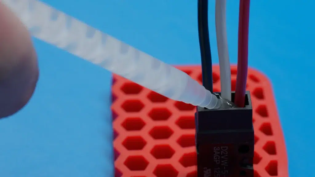
Sealing performance may depend on:
- Seal compression
- Potting volume
- Dispense location
- Surface preparation
- Adhesive application
- Cure conditions
- Component positioning
- Fixture control
Where Manufacturing Differences Can Affect Test Results
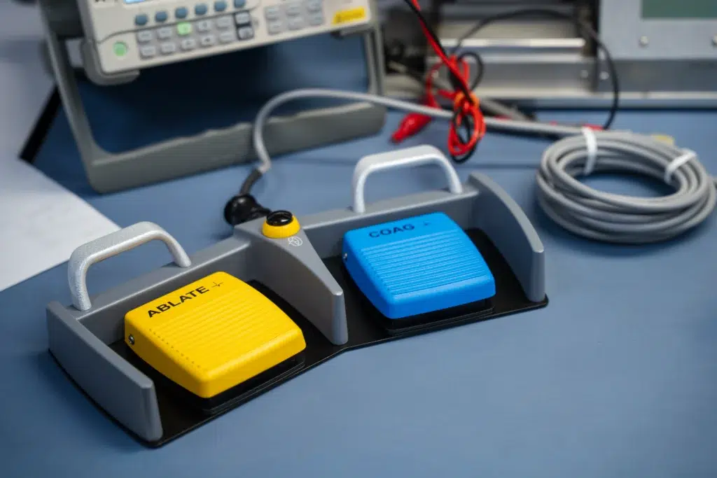
The concern is not simply that prototype units may perform poorly. In some cases, prototype units can perform better than routine production units because they are individually assembled, adjusted, inspected, and corrected by engineering personnel.
The issue is whether the units accurately represent the conditions that influence the requirement being evaluated.
Several areas are particularly sensitive to manufacturing method.
A unit assembled manually during development may have different sealing characteristics from one produced using the intended production process.
Where ingress protection or fluid resistance is being evaluated, these differences should be considered before concluding that the test results represent routine production.
Actuation Characteristics
Measurements taken from units assembled using a different method may not represent the performance distribution expected in production.
For medical foot and hand controls, this is particularly important when force, travel, or switching characteristics contribute to usability or functional performance.
Operating force, pretravel, switching point, return position, and post travel can be influenced by:
- Component stack up
- Switch position
- Spring installation
- Fastener torque
- Mechanical alignment
- Tolerance accumulation
- Fixture positioning
Electrical Performance
Dielectric strength, insulation performance, continuity, and isolation can depend on more than the electrical design alone.
Manufacturing characteristics such as conductor routing, termination method, insulation placement, potting coverage, component spacing, and cable preparation can influence electrical performance.
Where these characteristics are process controlled, the units used for testing should represent those production conditions.
Material Performance
Manufacturing processes can also influence material behavior.
Molding temperature, pressure, gate location, cooling conditions, machining, forming, and secondary processing can affect residual stress and material properties.
This can become important during impact, chemical compatibility, environmental, and durability testing.
A material sample or development component can provide useful early information, but final testing should consider whether the production process introduces characteristics that the development sample does not reproduce.
Verification and Validation Require
Different Considerations
Verification and validation serve different purposes, and the required level of production representativeness should be considered in that context.
Validation
Design validation evaluates whether the final product meets defined user needs and intended uses under actual or simulated use conditions.
For these activities, production representative units or appropriately justified equivalents are particularly important.
The closer the test unit is to the configuration that will be routinely supplied, the stronger the relationship between the validation evidence and the finished product.
Where differences remain, they should be documented and evaluated for their potential influence on the validation result.
Verification
Design verification demonstrates that specified design requirements have been met.
Prototype or development units can be appropriate for verification when the method used to produce them does not influence the requirement being evaluated.
For example, early prototypes may be suitable for evaluating:
- Interface dimensions
- Electrical logic
- Software functionality
- User interface concepts
- Certain mechanical requirements
Where the manufacturing process itself can influence the result, greater production representativeness may be required.
The important question is not simply whether the unit is a prototype. It is whether the differences between the prototype and intended production configuration could affect the requirement being verified.
The Relationship to Design Transfer
Design transfer establishes that the approved design has been correctly translated into manufacturing specifications and controls capable of producing the intended product.
Verification and validation results can support this activity, particularly where the tested units represent the manufacturing characteristics that influence performance.
The goal is not necessarily to require every test unit to be built on final production equipment. The goal is to understand and control the differences.
Where a difference between the test build and intended production process cannot influence the requirement being evaluated, a documented technical justification may be sufficient.
Where the difference could influence the result, additional evidence may be required.
Addressing these questions early in development can prevent a much larger testing effort later in the program.
That evidence could include:
- An engineering equivalence assessment
- Supplemental testing
- Bridging studies
- Targeted confirmation testing
- Testing of later production representative units
- Repetition of affected verification or validation activities
This can require completion of applicable activities such as:
- Production tooling development
- Process parameter definition
- Equipment qualification
- Inspection method development
- Manufacturing fixture development
- Work instruction development
- Process qualification or validation, where required
Production Readiness and Test Sequencing
Production representativeness creates an important sequencing consideration during development.
Before final validation units are built, the manufacturing methods that materially affect product performance should be sufficiently defined and controlled to produce representative units.
Not every piece of production tooling requires formal Installation Qualification and Operational Qualification. The level of qualification depends on the equipment, process, product risk, and applicable quality system requirements.
The objective is to establish sufficient control over the manufacturing process so that the units used for final testing can reasonably represent the product that will enter routine production.
Programs that delay these activities until after validation can create unnecessary risk. If later manufacturing changes affect a characteristic that was previously tested, the existing evidence may need to be reassessed.
Early coordination between design, manufacturing, quality, and testing teams reduces this exposure.
Evaluating Build Practice During Supplier Assessment
For medical device OEMs evaluating a component supplier, several questions can help determine whether supplier generated test evidence is representative of the product that will be supplied.
Were the units produced using production representative equipment, tooling, and processes where those conditions could affect the test result?
Were the assembly methods and process parameters used for test units documented?
Were applicable production equipment and processes sufficiently qualified or controlled before representative units were built?
Where differences existed, is there a documented technical justification demonstrating why they do not affect the test result?
Were differences between development and production methods identified and evaluated?
Can manufacturing and test records establish how the units were produced?
Clear answers to these questions provide greater confidence that supplier generated evidence is representative of the production product.
For a medical device OEM, this evidence can then be appropriately incorporated into device level verification, validation, risk management, design transfer, and technical documentation activities.
Summary
The medical foot control development process follows six phases and thirteen defined stages: concept definition, design collaboration, preliminary renderings, budgetary quotation, requirements refinement, prototype documentation, prototype quotation, prototype build and delivery, design refinement, production quotation, release documentation, verification and validation units, and production implementation. Verification and validation units are manufactured using the intended production equipment and processes so that units evaluated by the OEM are representative of the production configuration. Release documentation is completed as a defined stage ahead of production implementation. A working prototype can be available in as little as two weeks, and production programs range from approximately 100 to more than 100,000 units. The extent of departure from a standard platform determines verification scope, documentation requirements, tooling, and program cost, with limited changes potentially supported by existing design and verification evidence.
Frequently Asked Questions
What are the stages of a custom medical foot control program?
Concept definition, design collaboration, preliminary renderings, budgetary quotation, requirements refinement, prototype documentation, prototype quotation, prototype build and delivery, design refinement, production quotation, release documentation, verification and validation units, and production implementation.
How long does it take to obtain a custom medical foot control prototype?
A working prototype can be available in as little as two weeks. Actual timing depends on design scope, component availability, custom materials, electronic content, and how completely the application requirements are defined at intake.
Why are verification and validation units built using production equipment?
So that the units evaluated by the OEM are representative of the production configuration. Units produced through different equipment or methods generate data describing a configuration that will not be supplied.
Does a custom configuration require a separate UL listing?
Not necessarily. UL manages listing activities for applicable stock products, and a custom configuration derived from a listed platform may be able to use portions of the existing certification basis, subject to the nature of the modification and agency determination.
What production volumes can a custom medical foot control program support?
Production programs range from approximately 100 to more than 100,000 units.
When is release documentation completed?
Applicable records supporting the OEM product release are completed and provided as a defined stage positioned before production implementation, rather than assembled after design completion.
Discuss Your Medical Foot Control Program
Program scope, verification requirements, and documentation needs are established early in the sequence, and the decisions made during concept definition and requirements refinement determine how much of the program can rely on existing design and verification evidence.
Share the intended function, system interface, operating environment, expected annual volume, and target program timing with our engineering and applications teams to review whether an existing platform, a configured platform, or a fully custom medical foot control is appropriate for the program.
Meet The Author

Arijan Kandic
Digital Marketing Specialist
Arijan is the Digital Marketing Specialist at Linemaster Switch Corporation and holds a bachelor’s degree in business management from Quinnipiac University. He manages the company’s SEO strategy, Google Ads campaigns, and digital marketing initiatives, and develops educational content for the Linemaster Learning Center to help engineers, OEMs, and medical device manufacturers better understand foot switch technology. Arijan works closely with Linemaster’s engineering and applications teams to translate complex technical concepts into clear, accurate articles on foot switch design, customization, and compliance considerations.
In Collaboration with

Sean Lewis
Director of Engineering
Sean has more than fifteen years of experience in product development, engineering governance, and cross functional technical operations. His background in metal fabrication, including machining, forming, welding, and inspection, provides a strong manufacturing foundation that supports his approach to design and process optimization. Sean holds a bachelor’s degree in mechanical engineering, an MBA with a manufacturing concentration, and an MSOL. He is a Certified SolidWorks Expert with advanced capability in CAD, rendering, simulation, and rapid prototyping. Sean also specializes in DFMEA and PFMEA risk management practices and is the holder of several foot switch design and utility patents.
Uploaded 08/13/2026
Custom Foot Switches
Linemaster’s custom footswitches are designed to meet specific user requirements, offering a range of features such as various pedal configurations, wired and wireless options, and customizable LED indicators. These custom footswitches provide reliable, durable solutions tailored to enhance functionality in diverse applications.

