Types of Electronic Switches: A Complete List of Switch Types and Their Uses
Switches are one of the most fundamental components in electrical and electronic systems. They control when current flows through a circuit, allowing machines, devices, and control systems to start, stop, or change operating states.
Although the basic idea of a switch is simple, the phrase types of electronic switches can actually refer to several different characteristics. A switch might be classified by how many circuits it controls, how many connection paths it can switch between, what its contacts do at rest, or how it behaves when actuated.
Understanding these characteristics makes it easier to identify the right control solution for a specific application. This guide explains the different types of electronic switches commonly used in equipment and control systems, how they work, and where they are typically used.
What Is an Electronic Switch?
An electronic switch is a device that opens or closes an electrical circuit, allowing current to flow through it or be interrupted.
In many designs, this occurs when internal contacts move to connect or disconnect conductive paths. When the switch changes state, the connected device responds accordingly.
Electronic switches appear in a wide range of systems, including industrial machinery, laboratory instruments, and medical equipment. In many of these environments, switches act as the primary interface between an operator and a piece of equipment, allowing functions to be activated, stopped, or adjusted.

How Electronic Switches Are Classified
When discussing switch types, several characteristics are typically used to describe how a switch behaves.
One of the most common classifications is the number of poles, which describes how many electrical circuits the switch can control. Another is the number of throws, which indicates how many connection paths each pole can switch between.
Switches are also categorized by their contact state at rest. Some switches are normally open, meaning the circuit is disconnected until the switch is activated. Others are normally closed, meaning the circuit remains connected until the switch changes state.
Finally, switches can be categorized by their behavior when actuated. Some switches return automatically to their original position when released, while others remain in the selected state until they are actuated again.
Together, these characteristics form the basis for the different types of electronic switches used in real equipment and control systems.
Common Types of Electronic Switches
Product | Switch Type | Classification Type | Definition | How the Circuit Behaves | Typical Applications |
|---|---|---|---|---|---|
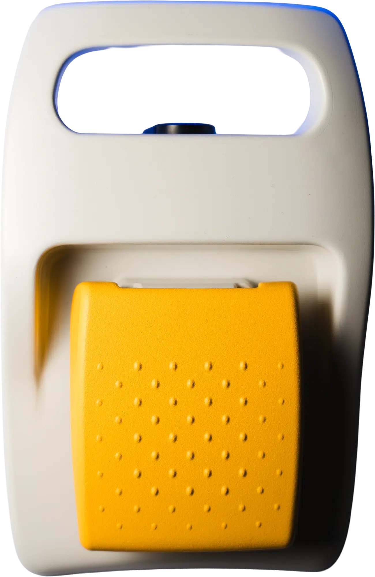
 | Single Pole Switch | Circuit Configuration | Controls one electrical circuit. A single set of contacts opens or closes one current path when the switch is actuated. | One circuit is either connected or disconnected. No other circuits are affected by the switching action. |
|
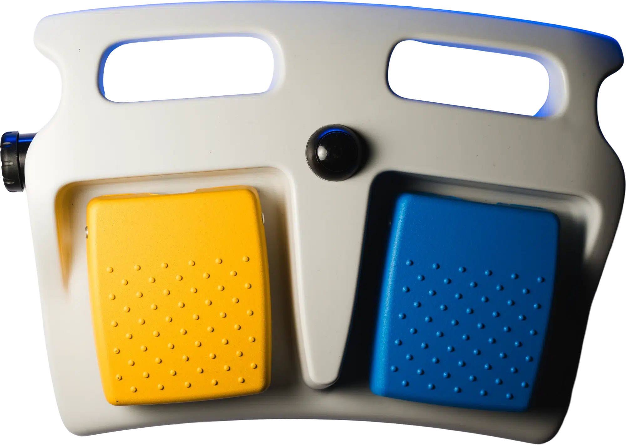
 | Double Pole Switch | Circuit Configuration | Controls two independent electrical circuits simultaneously with a single actuator. Both circuits change state at exactly the same moment. | Two circuits open or close together. Neither circuit can change state independently of the other in a double pole design. |
|
 | Single Throw Switch | Output path count | Connects or disconnects a single circuit path. Each pole has one possible output connection, producing a simple on/off switching action. | The circuit either connects to its one output or disconnects entirely. There is no alternative output path available. |
|
 | Double Throw Switch | Output path count | Routes a circuit between two possible output paths. Instead of simply opening or closing, the switch redirects the electrical connection from one output to another. | The circuit is always connected to one of two outputs. In the rest position it connects to the first output; when actuated it connects to the second. |
|
 | Normally Open Switch | Contact state at rest | Does not allow current to flow when the switch is at rest and no force is applied. The circuit closes only when the operator actuates the switch. | Circuit is open at rest; current flows only during actuation. If the switch fails or loses power, the circuit remains open and connected equipment does not activate. |
|
 | Normally Closed Switch | Contact state at rest | Allows current to flow continuously when the switch is at rest. Actuating the switch opens the circuit and interrupts current flow. | Circuit is closed at rest; current stops only during actuation. If the switch fails or a wire breaks, the circuit opens and connected equipment stops. |
|
 | Momentary Switch | Switching behavior | Returns automatically to its original position the instant the operator releases pressure. The switch is active only while being pressed or held down. | Output signal duration equals exactly the duration of operator actuation. The circuit resets the moment foot pressure is removed, with no latching or holding action. |
|
 | Maintained Switch | Switching behavior | Stays in its new position after actuation and holds that state until the operator actuates it again to change it. Also called a latching switch. | Output signal continues indefinitely after the operator releases the switch. A second actuation is required to return the switch to its original state. |
|
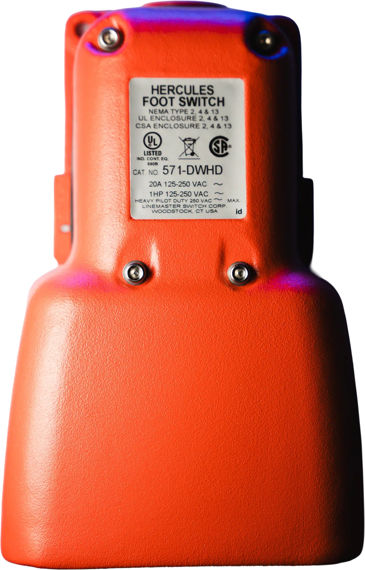
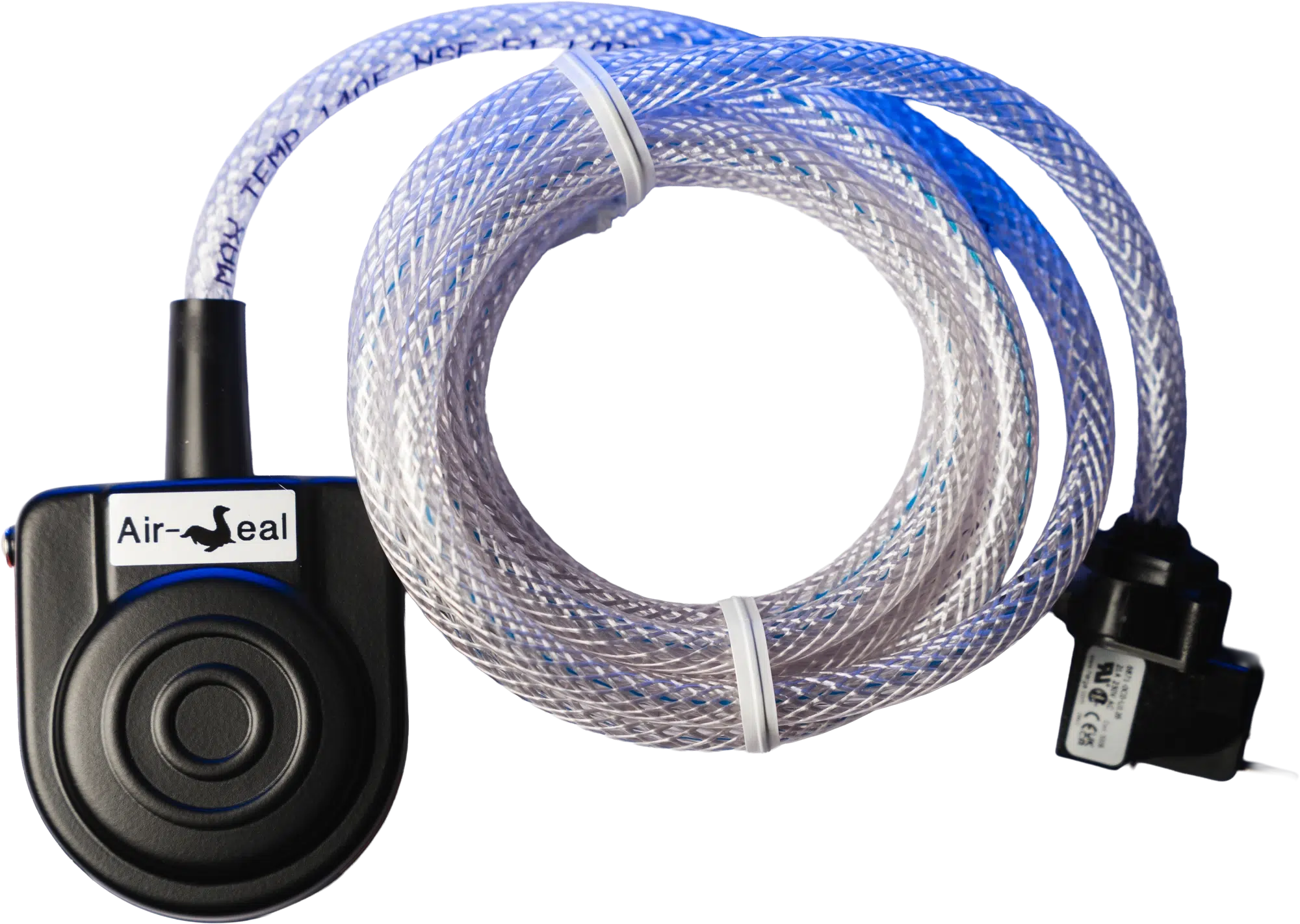 | Pneumatic Switch | Actuation technology | Uses air pressure to trigger a switching action rather than direct electrical contact at the actuation point. Pressing the foot switch generates air pressure that activates a remote electrical component. | No electrical circuit is present at the foot switch itself. The air signal travels through tubing to a remote electro-pneumatic valve or pressure switch that changes the electrical circuit state. |
|
 | Wireless Switch | Connectivity | Transmits the switching signal to the equipment without a physical cable. The foot switch communicates via RF (900 MHz or 2.4 GHz) or Bluetooth Low Energy to a receiver connected to the equipment. | Switching signal is encoded and transmitted wirelessly. RF wireless systems achieve latency of 20 to 40 milliseconds. Wired systems are instantaneous. Both are suitable for most medical and industrial control functions. |
|
 | Solid State Switch | Internal technology | Controls current using semiconductor components rather than mechanical contacts that physically touch. No moving parts are involved in the switching action itself. | Current is controlled electronically. No contact arcing occurs. Switching speed is faster than mechanical designs. Signal integrity is not affected by contact bounce, wear, or oxidation over time. |
|
Configuration | Full Name | Poles | Throws | How it Works | Common Applications | Shop |
|---|---|---|---|---|---|---|
SPST | Single pole, single throw | Controls one circuit with one connection path. Provides simple on/off switching with no routing between outputs. |
| |||
SPDT | Single pole, double throw | Controls one circuit but routes it between two possible output paths. Allows switching between two distinct operating states using a single actuator. |
| |||
DPST | Double pole, single throw | Simultaneously opens or closes two independent circuits using one actuator. Useful when two conductors must be switched together for complete electrical disconnection. |
| |||
DPDT | Double pole, double throw | Controls two independent circuits simultaneously, each switchable between two output paths. Used when two circuits must reverse states or redirect signals at the same moment. |
|
Choosing the Right Switch Type
Selecting the correct switch type depends on several factors related to how the equipment will operate.
Engineers often evaluate electrical ratings such as voltage and current capacity, environmental conditions such as moisture or contaminants, and the type of interaction required between the operator and the equipment.
Other considerations include whether one or multiple circuits must be controlled, whether the switch should return automatically after activation, and whether safety related switching behavior is required.
Understanding these factors help determine which switch configuration best supports the intended application.
Conclusion
Electronic switches play a critical role in the operation of electrical systems. While every switch performs the basic function of opening or closing a circuit, the many types of switches available today allow designers to tailor control behavior to the needs of specific equipment and environments.
By understanding the different types of electronic switches and how they function, engineers and equipment designers can make more informed decisions when selecting the right control interface for their applications.

Frequently Asked Questions
How do I choose between switch types based on the environment?
Environmental conditions influence switch selection. Moisture, vibration, chemicals, or frequent activation may require you to select switches with specific sealing, materials, or durability characteristics.
How do I estimate wireless switch battery life for my use case?
Wireless switch battery life depends on several factors, including activation frequency, communication method, and power management design. Systems that are actuated more frequently will typically consume battery power more quickly.
What does forced disconnect or positive break mean?
Forced disconnect, also called a positive break, is a switching mechanism in which the actuator physically separates the electrical contacts. This mechanical separation helps ensure that the circuit is fully opened when the switch changes state.
Meet The Author

Arijan Kandic
Digital Marketing Specialist
Arijan is the Digital Marketing Specialist at Linemaster Switch Corporation and holds a bachelor’s degree in business management from Quinnipiac University. He manages the company’s SEO strategy, Google Ads campaigns, and digital marketing initiatives, and develops educational content for the Linemaster Learning Center to help engineers, OEMs, and medical device manufacturers better understand foot switch technology. Arijan works closely with Linemaster’s engineering and applications teams to translate complex technical concepts into clear, accurate articles on foot switch design, customization, and compliance considerations.
In Collaboration with

Sean Lewis
Director of Engineering
Sean has more than fifteen years of experience in product development, engineering governance, and cross functional technical operations. His background in metal fabrication, including machining, forming, welding, and inspection, provides a strong manufacturing foundation that supports his approach to design and process optimization. Sean holds a bachelor’s degree in mechanical engineering, an MBA with a manufacturing concentration, and an MSOL. He is a Certified SolidWorks Expert with advanced capability in CAD, rendering, simulation, and rapid prototyping. Sean also specializes in DFMEA and PFMEA risk management practices and is the holder of several foot switch design and utility patents.
Uploaded 04/08/2026
Custom Foot Switches
Linemaster’s custom footswitches are designed to meet specific user requirements, offering a range of features such as various pedal configurations, wired and wireless options, and customizable LED indicators. These custom footswitches provide reliable, durable solutions tailored to enhance functionality in diverse applications.
